
 Log Masuk
Understanding the MG5114A Marine Gear For Twin Disc MG-5114A Marine Gear
Salma W
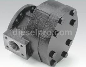

The Twin Disc MG-5114A is one of the most trusted transmissions in the commercial marine industry. Known for its durability and dependable performance under constant load, the MG-5114A was engineered for long service life in tough marine environments. It’s frequently installed in vessels that operate around the clock—tugboats, pilot boats, work barges, fishing vessels, and utility crafts—where reliability isn’t a luxury, it’s a requirement.
To maintain and troubleshoot this gear effectively, a deeper understanding of its technical specifications and internal components is essential. This section provides that foundation, breaking down both the performance characteristics and the critical components that make up the MG-5114A transmission system.

Parts Catalog for Twin Disc MG5114A Marine Transmissions Plate Kit For Twin Disc MG5114A Marine Transmission Gasket Kits For Twin Disc MG5114A Marine Transmission
Key Specifications for Twin Disc MG5114A Marine Gear
While many operators are concerned only with the basic fitment and operation of the unit, understanding its rated capabilities and design parameters helps you avoid overloading the gear or creating heat and wear issues that lead to failure. Below are the key specs that define how this transmission operates and what it's capable of handling.
Rated Horsepower and Torque Capacity
The MG-5114A is built for continuous-duty operations. Depending on the configuration and reduction ratio, the transmission can handle input power ratings in the ballpark of:
- Up to 500 horsepower (373 kW) at continuous duty
- Torque capacity ranging between 1,500 to 2,000 lb-ft depending on the internal gearing and model variant
- Suitable for both light and heavy-duty marine diesel engines
Input Speed and Reduction Ratios
Twin Disc designed the MG-5114A to accommodate diesel engines operating in the 1,800 to 2,100 RPM range—standard for most marine applications.
The gear is available in multiple reduction ratio configurations, typically ranging from:
- 1.54:1
- 1.97:1
- 2.43:1
- 2.96:1
- 3.47:1
- 4.00:1
- A lower reduction ratio (e.g., 1.54:1) is best for faster vessels that need speed and efficiency
- A higher reduction ratio (e.g., 4.00:1) is ideal for vessels that prioritize pulling power, such as trawlers and push boats
Weight and Dimensions
The MG-5114A is compact and lightweight for the torque it handles:
- Approximate dry weight: ~850 lbs (386 kg)
- Length: Approximately 24–30 inches (varies based on mounting and ratio)
- Width and height: Designed to fit within typical marine engine compartments, with clearance for servicing
Mounting Configurations and Rotation
The MG-5114A can be ordered in several configurations, allowing for flexible installation options:
- SAE #1 and SAE #2 housing configurations
- Flexible and rigid mounts available depending on engine and hull requirements
- Vertical and offset mounting compatibility
- Can be configured for opposite rotation or same rotation depending on the propeller setup and twin-screw needs
Component Overview for Twin Disc MG5114A Marine Gear
The MG-5114A consists of several key assemblies that work together to transfer power from the engine to the propeller shaft with minimal loss. Understanding each major part and how they interact gives you a much clearer path to diagnosing problems or scheduling preventive maintenance.
Input Shaft and Damper Coupling
The input shaft receives torque from the engine's flywheel, and it is typically splined to accept a torsional damper plateor coupling. The damper coupling absorbs engine pulsations and smooths out vibration, which protects the internal gearing and clutch packs from shock loading.
A few things to keep in mind:
- Worn damper plates are a common source of rattling, clunking, or chatter at idle
- Misalignment between the engine and input shaft can lead to premature input bearing wear or spline damage
- If you’re removing the transmission, always inspect the damper for cracks, worn springs, or loose hardware
Clutch Assemblies (Forward and Reverse)

At the heart of the transmission’s power-transfer system are the forward and reverse clutch packs. These multi-disc clutch assemblies use hydraulic pressure to engage or disengage based on the vessel's gear selection.
Each clutch pack consists of:
- Friction discs (clutch plates)
- Steel separator plates
- Apply pistons
- Return springs or snap rings
- Hydraulic actuators
Common service points include:
- Inspecting clutch plate thickness and wear pattern during rebuilds
- Replacing friction and steel plates as a matched set
- Ensuring hydraulic circuits are clean and pressure-regulated
Gear Train (Helical Gear Arrangement)
The gear train is where the magic happens—translating high-speed engine output into low-speed, high-torque shaft rotation via the chosen reduction ratio. The MG-5114A typically uses a helical gear configuration, which provides:
- Smoother and quieter operation than spur gears
- Higher load-carrying capacity
- Greater durability under constant load
- Whining noises at high speed
- Metal flakes in oil filters
- Backlash beyond tolerance
During servicing or rebuilds:
- Inspect gear teeth for pitting, scoring, and micro-fractures
- Check backlash with feeler gauges and refer to OEM specs
- Always replace gears in matched sets if worn
Output Shaft and Companion Flange
The output shaft transmits power to the propeller shaft through a bolted companion flange or coupling. This part of the transmission is under continuous torque and must be perfectly aligned to prevent bearing and seal wear.
Key things to know:
- Output seals are common leak points, especially with aged or cracked rubber components
- Excessive shaft play or end float can indicate worn output bearings or housing bushings
- When aligning the flange to the propeller shaft, check for runout and face alignment using a dial indicator
The companion flange should be removed carefully during servicing, and all fasteners should be torqued to spec with thread locking compound if required.
Hydraulic System and Oil Pump

The MG-5114A’s hydraulic system is powered by a gear-driven oil pump, usually mounted internally on the front housing. This pump is responsible for circulating transmission fluid to:
- Actuate the clutch packs
- Lubricate bearings and gears
- Feed the oil cooler and return lines
- Clutch packs may fail to engage properly
- Heat buildup may destroy fluid and cause seal failure
- Bearings may not receive enough lubrication
- Check oil pressure with a calibrated gauge
- Replace or clean inlet strainers and oil filters
- Flush oil lines and coolers during rebuilds
Control Valve and Actuators
The control valve assembly manages hydraulic pressure flow to the forward or reverse clutch packs based on the operator’s shift lever or electronic control input.
Depending on your setup, this may be:
- A mechanical control valve with linkage connected to a helm lever
- An electronic solenoid-actuated valve integrated into a digital control system
- Spool valves
- Pressure regulators
- Shift solenoids (if equipped)
- Detent springs and guides
During maintenance:
- Disassemble valves carefully and work in a clean environment
- Check for scoring, corrosion, or stuck spools
- Replace any questionable O-rings or seals
- Reassemble using torque specs and lubrication as required
Plate Kit For Twin Disc MG5114A Marine Transmission Gasket Kits For Twin Disc MG5114A Marine Transmission
Videos About Twin Disc Transmissions
6 Reasons Your Twin Disc Transmission Has Low Oil Pressure
7 Reasons Your Twin Disc Transmission Is Overheating
3 Reasons Your Clutch Plates in Your Twin Disc Transmission Are Making Excessive Noise
Bull Gear On A Twin Disc Transmission
Rebuilt Twin Disc Transmissions